The time unit size, such as ns or ps, is specified in the logic library.īy default, the tool assumes that signals are propagated through each data path in one clock cycle. The clock period is defined in the tool to be 10 time units. The following example shows how STA checks setup and hold constraints for a flip-flop:įor this example, assume that the flip-flops are defined in the logic library to have a minimum setup time of 1.0 time units and a minimum hold time of 0.0 time units. This constraint enforces a minimum delay on the data path relative to the clock edge.


STA then checks for violations of timing constraints, such as setup and hold constraints: This delay is caused by the parasitic capacitance of the interconnection between the two cells, combined with net resistance and the limited drive strength of the cell driving the net. Net delay is the amount of delay from the output of a cell to the input of the next cell in a timing path. From these table entries, the tool calculates each cell delay.

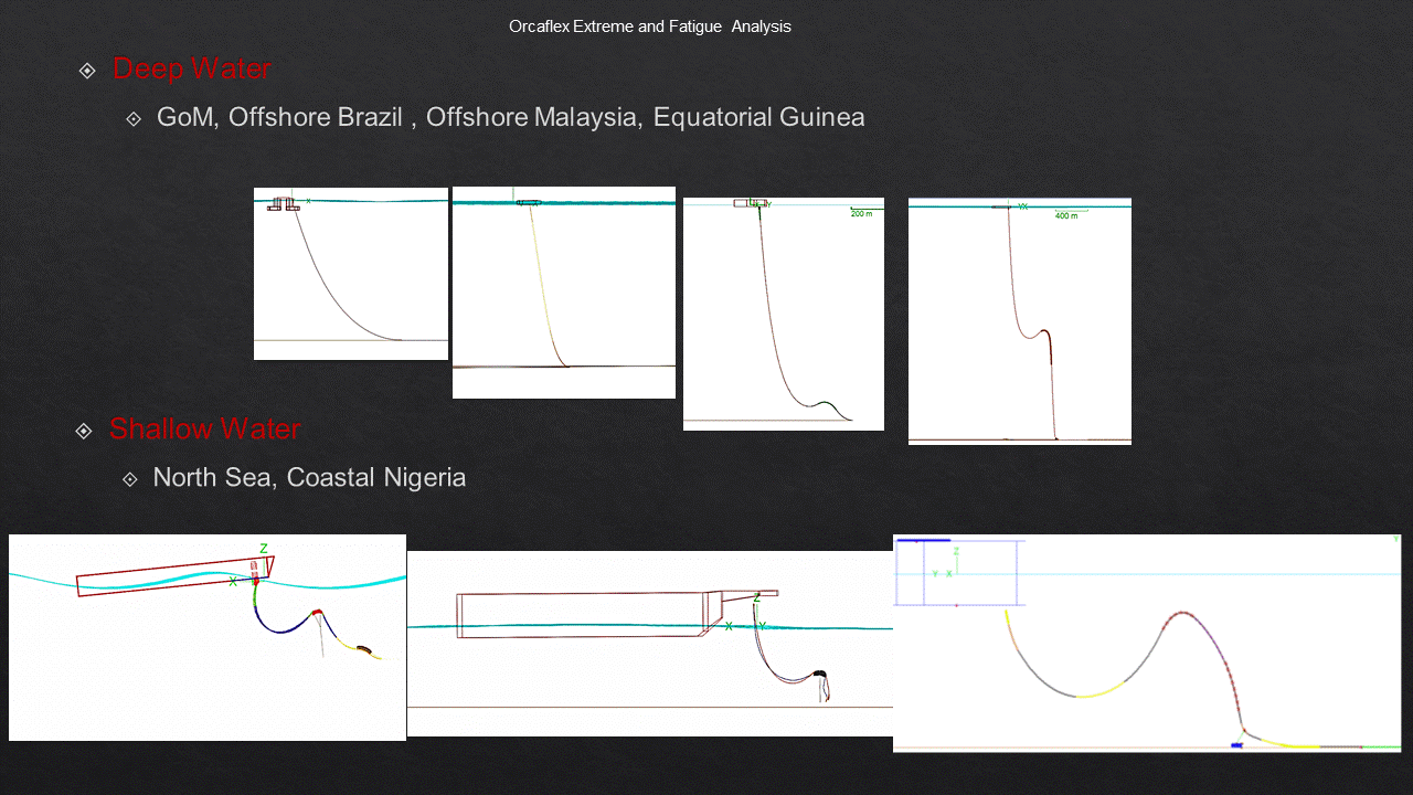
Typically, a delay table lists the amount of delay as a function of one or more variables, such as input transition time and output load capacitance. In the absence of back-annotated delay information from an SDF file, the tool calculates the cell delay from delay tables provided in the logic library for the cell. The total delay of a path is the sum of all cell and net delays in the path.Ĭell delay is the amount of delay from input to output of a logic gate in a path. Based on the stresses obtained in the longitudinal and circumferential directions, the selection of suitable section dimensions for an SFT is considered.After breaking down a design into a set of timing paths, an STA tool calculates the delay along each path. These were used mainly for longitudinal dynamic analysis and 3-D stress evaluation, respectively, of an SFT. The validation of each equivalent static load was supported by the results from comparison of the tension forces in mooring lines obtained using OrcaFlex and ABAQUS.

Upon consideration of the static responses equivalent to the dynamic behavior, three-dimensional (3-D) finite-element analyses of an SFT were performed by application of static loads corresponding to dynamic loads equivalent to those of wave, current and earthquake. Accordingly, a supplementary approach by which to obtain structural responses in the circumferential direction is introduced in this paper. This means that SFT design requires additional information on the structural behavior of the tunnel in the circumferential direction for efficient design. Even though these analyses give sufficient information in the longitudinal direction, too little information about the circumferential direction compels an SFT section to be designed conservatively. However, the complex interaction between an SFT and surrounding fluid has confined most research on SFTs to longitudinal global time-history analyses based on Morison's equation. Stress evaluation of a submerged floating tunnel (SFT) is an issue important for determining the section dimensions required to resist environmental loads.


 0 kommentar(er)
